


Power quality monitoring, and in particular harmonic measurement, is becoming more and more critical in the power system. This is going around for many years, but recently it has also arrived to High Voltage systems.
With the increased presence of Renewable Energies, in particular solar and wind power, and their use of inverter-based technologies, harmonic presence in High Voltage substations, particularly those connected to RE plants, has become an issue that needs to be addressed.
In order to control and reduce the presence of harmonics in the HV network, they have to be detected and measured, and the first question that would come to our mind is:
Can conventional instrument transformer measure harmonics accurately?
There are several viable alternatives in the market to measure current harmonics with conventional and non-conventional instrument transformers. Additional to conventional current transformers based on inductive technology, we can use Rogowski coils, Optical or Hall effect technology, … They all have enough bandwidth to offer reasonable accuracy up to values well above 10kHZ.
Arteche’s experience with HV conventional CTs is shown in the Fig. 1. Although the error increases with the frequency, it’s still within reasonable limits (ie. 0.6% at 3.5kHz), so the use of conventional CTs for measuring is accurate also for harmonic measurement.
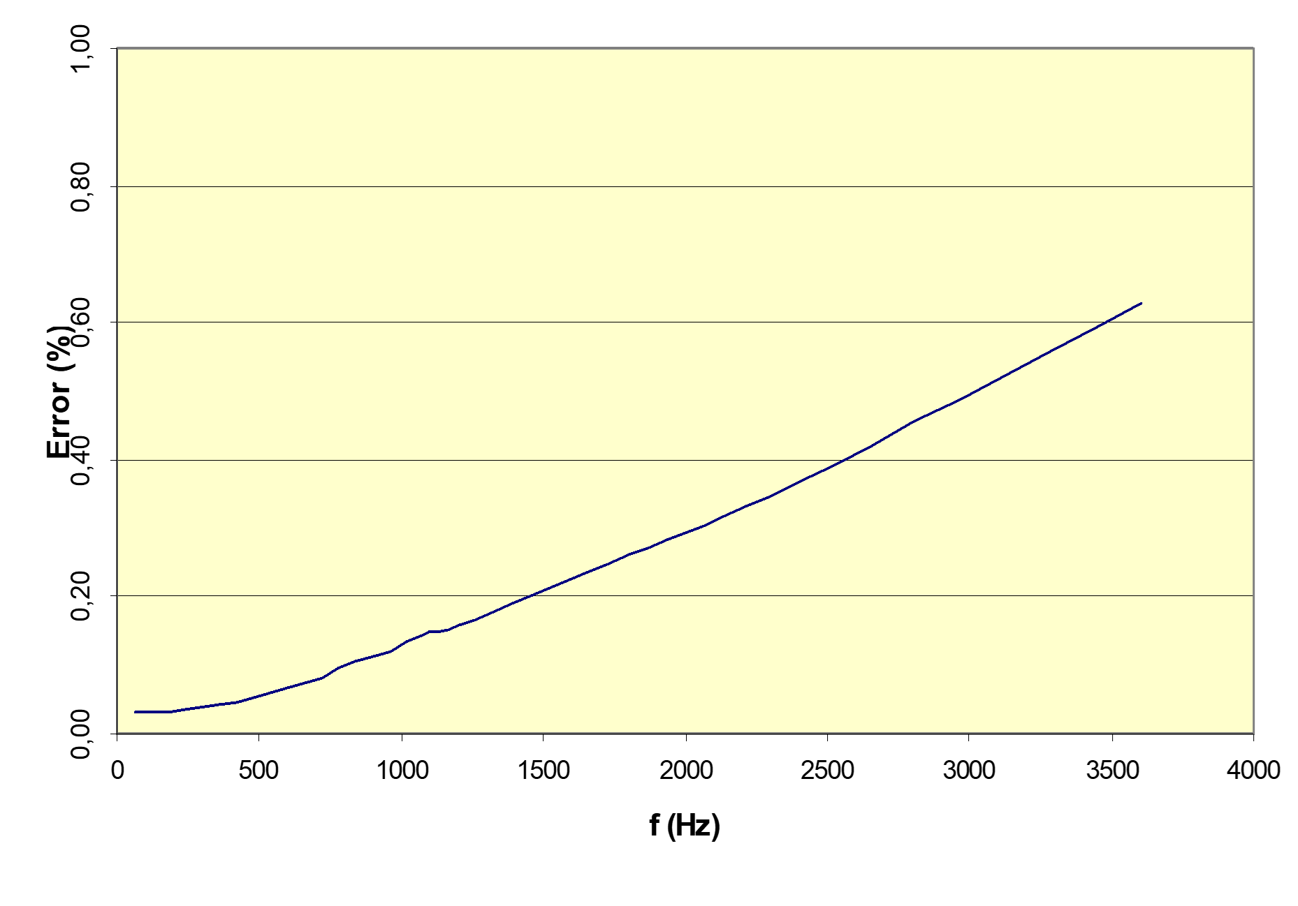
Fig.1: Ratio error results after testing of a conventional current transformer with metering core.
However, measuring voltage harmonics is more complicated. Similar to CTs, there are alternative technologies that allow high frequency voltage measurements, but for conventional VTs not all the available technologies perform properly and there are some issues that need to be addressed. There are two technologies for conventional high voltage transformers:
- Inductive voltage transformers show a resonance frequency that can distort the measurement. It is important to guarantee that this frequency is above the last harmonic we need to measure. This frequency depends on various parameters such as primary coil geometry, stray flux…, it is usually above 1kHz, and it changes from model to model, therefore it’s not possible to establish a general rule applicable to all designs and manufacturers.
In the Fig. 2 we can see the test results of two different IVTs manufactured by Arteche.
Fig. 2: Ratio error results after testing of 72kV and 145kV inductive voltage transformer
- Capacitive voltage transformers are tuned at a specific frequency (50 or 60Hz), and out of there, the errors increase. Therefore, they cannot be used for harmonic measurement with any further adjustment. By using an accessory such as PQSensor® added to the CVT, it can be used for quality monitoring. This solution is valid for any voltage level and up to 20 KHz with errors up to 2%, some experience results can be seen in Fig. 3.

Fig. 3: Ratio error results of a CVT with PQSensor® devic
However, when the installation additional components is not feasible, Arteche has developed a method to undo the effect of the CVTs on the harmonic measurements.
This research was presented during the 4th International Conference on Smart Energy Systems and Technologies ?[4º IEEE SEST - International Conference on Smart Energy Systems and Technologies] and achieved the recognition of best presentation of the conference. If you want to know more about this methodology, do not hesitate to consult the article "Harmonic Measurements in a Capacitive Voltage Transformer: Improvement Considering the Transformer's Design Parameters", by clicking here.
Conclusions:
When measuring current and voltage harmonics in an existing substation, the following considerations must be taken into account:
Current Transformers: The same unit used for 50/60Hz measurement for metering and relaying can also be used with a reasonably good accuracy for higher frequencies. However, we need to consider that this accuracy decreases with the frequency, still within acceptable limits.
Inductive VTs: The IVTs already placed in the substation for metering and relaying at 50/60Hz still provide a reasonably good accuracy for lower harmonics. However, there is a resonant frequency at 1-2kHz that limits the accuracy of the measurement at higher harmonics. Some kind of correction is needed based on the transformer design.
Capacitive VTs: CVTs can’t take accurate harmonic measurement, even for the lower harmonics, without further adjustment. By using an accessory such as PQSensor®, the accuracy is maintained though a bandwith above 10kHz making them accurate for both 50/60Hz and harmonic measurements.
Another option is to carry out an analysis to undo the effect of the TTCapacitive, knowing its parameters, thus obtaining a reliable image of the harmonics present in the network.


